Typical Calibration Requirements For 360° Camera View
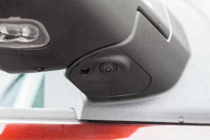 Shown is the 360 Camera on a 2015 Ford Explorer.
 Technicians should be aware of what’s required to keep advanced driver assistance systems (ADAS) running safely after a collision. Whether that be aiming a camera, which can cause a system to not function as intended, or checking for diagnostic trouble codes (DTCs). For a basic understanding of what’s required, we’ve put together a series of articles that provide general information on what’s required to repair the system after a collision. Let’s take a look at 360° Camera View systems.
The 360° Camera View shows a bird’s-eye view of the vehicles surroundings. This system will utilize multiple cameras in different locations around the vehicle. Cameras can be found in the front bumper/grille, under the side rearview mirrors, and in the deck lid/liftgate/tailgate. Calibration of all of the cameras is normally required after the replacement of any of the cameras. However, some OEMs require calibration when a side mirror is removed, bumper cover is removed, or when a door is removed.
The calibration process is normally a static calibration (in-shop procedure). Large mats are placed on the ground around the vehicle, then a scan tool starts an aiming procedure. Another method for calibration is dynamic calibration (on-road procedure). The aiming procedure is initialized and then the vehicle is driven slowly down the road under certain conditions.
Being informed on these systems is important to a complete, safe, and quality repair. Many consumers are purchasing a certain vehicle specifically for these driver assistance features. The consumer knows the system is on their vehicle and they are relying on it to help keep them safe. Therefore, technicians also need to be aware when driver assistance systems exist and have the knowledge to properly repair the system.
Additional I-CAR Collision Repair News you may find helpful:
- ADAS, Calibration, And Scanning Article Hotspot
- Collision Repair Diagnostics Definitions
- Typical Calibration Requirements
Related I-CAR Courses
Article validated in 2025
-
Toyota/Lexus/Scion Position Statement: Pre- and Post-Repair System Scanning
Thursday, 28 July 2016
As the industry continues to ask if pre- and post-repair system scanning is necessary, Toyota/Lexus/Scion provides their answer.
-
Pre- and Post-Repair System Scanning Statements
Wednesday, 9 January 2019
Are you wondering if a particular OEM or organization has a published statement on pre-repair and post-repair scanning? We have compiled a list of most of the statements on the subject, so you can...
-
ADAS, Calibration, And Scanning Article Hotspot
Monday, 14 January 2019
Since advanced driver assistance systems (ADAS), scanning, and calibration first started becoming relevant, members of the collision repair industry have required as much knowledge as possible on...
-
BMW Position Statement: Pre- and Post-Repair System Scanning - UPDATE
Friday, 10 April 2020
BMW has released a position statement related to pre- and post-repair system scanning. The statement applies to All vehicles equipped with on board diagnostics II (OBD II).
-
Honda/Acura Position Statement: Pre- and Post-Repair System Scanning - UPDATE
Wednesday, 22 May 2019
Honda /Acura has updated their position statement on pre- and post-repair scanning to give more clarification on what is expected for scanning.
-
Quickly Identifying Outer Quarter Panels w/Rolled Hem Flanges
Monday, 5 March 2018
The I-CAR best practice article, Recycled Outer Quarter Panels w/Rolled Hem Flanges has gotten a lot of interest from the collision repair industry. It’s important to know which vehicles are...
-
General Motors Position Statement: Pre- and Post-Repair System Scanning
Friday, 21 October 2016
As the industry continues to ask, are pre- and post-repair scans necessary, General Motors provides their answer.
-
Restraints Wiring Repairs
Monday, 23 May 2016
Over the past few months, we've been sharing OEM position statements on restraints wiring repairs. Now we're bringing them all together in one place for easy reference.
-
FCA/Stellantis Position Statement: Pre- and Post-Repair System Scanning
Thursday, 9 June 2016
FCA/Stellantis has released a position statement related to pre- and post-repair system scanning.
-
Typical Calibration Requirements For Forward Radar Sensors
Wednesday, 12 October 2016
Technicians should be aware of what’s required to keep advanced driver assistance systems (ADAS) running safely after a collision. Whether that be aiming a camera, which can cause a system to not...
-
Body Repair Manual Symbols: Ford/Lincoln
Wednesday, 11 February 2026
While looking at repair procedures in a body repair manual (BRM) you may notice that symbols are used to indicate specific operations or parts to be used during the repair process. Most BRMs provide a...
-
I-CAR Repairers Realm: I-CAR Registered Apprenticeship Program - Coming Soon
Monday, 9 February 2026
I-CAR is having a discussion on the Registered Apprenticeship Program (RAP).
-
SEMA 2025: Lucid Motors Body Repair Team - The New Gravity SUV
Friday, 6 February 2026
I-CAR had numerous presentations at the 2025 SEMA show. One of these presentations focuses on Lucid Motors Gravity SUV repair information.
-
Calibration Research Tips: Blind Spot Indicator In Side Mirrors
Wednesday, 4 February 2026
While searching for information on advanced driver assistance systems (ADAS) on an OEM repair information site, you may come across unique calibration procedures or events. These events can vary by...
-
Bumper Cover Repair With ADAS: BMW/Mini - UPDATE
Tuesday, 3 February 2026
A simple bumper repair on a modern vehicle may not be as simple as it seems. New technologies like blind spot monitoring, adaptive cruise control, and other advanced driver assistance systems (ADAS)...
-
Hyundai/Genesis Part Replacement Without A Procedure
Thursday, 29 January 2026
We are often asked, “What do I do if there isn’t a procedure to replace a service part?” Let’s see what Hyundai/Genesis says.
-
Kia Part Replacement Without A Procedure
Thursday, 29 January 2026
We are often asked, “What do I do if there isn’t a procedure to replace a service part?” Let’s see what Kia says.
-
I-CAR Repairers Realm: New In 2026: I-CAR Academy - Now Available
Wednesday, 28 January 2026
I-CAR staff had a discussion on the I-CAR Academy.
-
Battery Backup And Low-Voltage Disconnect: Toyota/Lexus
Thursday, 22 January 2026
When an accident happens, how will you call for help? Maybe the telematics system, equipped with a backup battery, could automatically do this, even if the main power is cut off. What are the repair...
-
Your 2025 Favorites: Top 20 Sectioning and Partial Part Vehicles
Wednesday, 21 January 2026
Now that the new year is underway, let’s take a look at your 2025 favorite vehicles in the OEM Partial Part Replacement Search.
- 2026
- February 2026 (5)
- January 2026 (11)
- 2025
- December 2025 (8)
- November 2025 (11)
- October 2025 (13)
- September 2025 (11)
- August 2025 (12)
- July 2025 (11)
- June 2025 (11)
- May 2025 (11)
- April 2025 (13)
- March 2025 (12)
- February 2025 (11)
- January 2025 (12)
- 2024
- December 2024 (8)
- November 2024 (10)
- October 2024 (13)
- September 2024 (10)
- August 2024 (12)
- July 2024 (11)
- June 2024 (9)
- May 2024 (13)
- April 2024 (12)
- March 2024 (12)
- February 2024 (12)
- January 2024 (9)
- 2023
- December 2023 (8)
- November 2023 (12)
- October 2023 (11)
- September 2023 (11)
- August 2023 (12)
- July 2023 (9)
- June 2023 (11)
- May 2023 (12)
- April 2023 (11)
- March 2023 (12)
- February 2023 (10)
- January 2023 (11)
- 2022
- December 2022 (11)
- November 2022 (12)
- October 2022 (11)
- September 2022 (13)
- August 2022 (11)
- July 2022 (10)
- June 2022 (13)
- May 2022 (11)
- April 2022 (12)
- March 2022 (10)
- February 2022 (11)
- January 2022 (13)
- 2021
- December 2021 (13)
- November 2021 (11)
- October 2021 (13)
- September 2021 (14)
- August 2021 (12)
- July 2021 (15)
- June 2021 (17)
- May 2021 (11)
- April 2021 (14)
- March 2021 (20)
- February 2021 (14)
- January 2021 (14)
- 2020
- December 2020 (13)
- November 2020 (17)
- October 2020 (12)
- September 2020 (14)
- August 2020 (11)
- July 2020 (18)
- June 2020 (14)
- May 2020 (14)
- April 2020 (19)
- March 2020 (12)
- February 2020 (13)
- January 2020 (14)
- 2019
- December 2019 (13)
- November 2019 (19)
- October 2019 (25)
- September 2019 (20)
- August 2019 (22)
- July 2019 (23)
- June 2019 (20)
- May 2019 (19)
- April 2019 (20)
- March 2019 (20)
- February 2019 (18)
- January 2019 (17)
- 2018
- December 2018 (18)
- November 2018 (19)
- October 2018 (17)
- September 2018 (16)
- August 2018 (21)
- July 2018 (20)
- June 2018 (21)
- May 2018 (16)
- April 2018 (19)
- March 2018 (21)
- February 2018 (15)
- January 2018 (20)
- 2017
- December 2017 (13)
- November 2017 (15)
- October 2017 (19)
- September 2017 (20)
- August 2017 (19)
- July 2017 (18)
- June 2017 (19)
- May 2017 (18)
- April 2017 (13)
- March 2017 (18)
- February 2017 (10)
- January 2017 (11)
- 2016
- December 2016 (9)
- November 2016 (14)
- October 2016 (21)
- September 2016 (10)
- August 2016 (11)
- July 2016 (8)
- June 2016 (10)
- May 2016 (5)
- April 2016 (11)
- March 2016 (12)
- February 2016 (10)
- January 2016 (8)
- 2015
- December 2015 (9)
- November 2015 (6)
- October 2015 (8)
- September 2015 (7)
- August 2015 (11)
- July 2015 (7)
- June 2015 (5)
- May 2015 (7)
- April 2015 (8)
- March 2015 (8)
- February 2015 (9)
- January 2015 (10)
- 2014
- December 2014 (12)
- November 2014 (7)
- October 2014 (11)
- September 2014 (10)
- August 2014 (9)
- July 2014 (12)
- June 2014 (9)
- May 2014 (12)
- April 2014 (9)
- March 2014 (6)
- February 2014 (1)
- January 2014 (26)
